We are about to recommend remote controller which is applied to both motor and lamp. It is DC12V momentary &toggle remote controller (S1F-DC12 & C-3-2), which features in motor forward-reverse capability. You can rotate the motor in positive or reversal direction by transmitter from any place within a reliable distance, wireless signal pass through walls, floors and doors. It is suitable for the motors of rolling blinds / doors, projection screens, awnings, pumps, winches, conveyors or other appliances and mechanicals with voltage DC12V. We also design lamp controlling function so that you can control motor and lamp with the same transmitter.
2014/07/31

2014/05/15
AC 220V Output Remote Controller for Electric Shutter
Overview:
I want to buy a radio system for my 9 shutters (220 V), wireless control, 9 receivers and 1 remote, climb or descend in all my components by one remote.

Solution:
We recommend ac power output controller (S1FM-AC220), which is designed for controlling motor specially. It can remote control many kinds of motor, rolling blinds/ doors, projection screens, awnings, winches, conveyors… 10amps is its maximum current. And when it works with the long distance transmitter (CB-2), the whole kit’s transmitting distance will reach 1000m.

Connect live wire to terminal “L” and neutral wire to terminal “N”. Then connect AC motor to terminals “UP”, “COMMON” and “DOWN”. You can exchange “UP” and “DOWN” wires of motor to change rotating direction of motor. 9 shutter motors should be wired to 9 receivers respectively. 9 receivers will be programmed the same code so that they can work together with one remote.

There is only one working mode in this controller. It is inversion control mode(Press and hold big button→positive rotation; press and hold small button→reversal rotation )
Press and hold big button, terminals UP and COMMON directly output AC 220; 9 shutter motors rotate continuously in positive direction at the same time.
Release big button, stop 9 shutter motors simultaneously.
Press and hold small button, terminals DOWN and COMMON directly output AC 220; 9 shutter motors rotate continuously in reverse direction at the same time.
Release small button, stop 9 shutter motors simultaneously.
2014/04/30
2000m Momentary Controller for DC Motor
Question from customer:


I am looking for a radio transmitter receiver 1 channel, 24V, 500 to 1000m, and function: I support the button, close the relay; I loose the button, open the relay.
Answer:
We recommend the model of 1 channel Momentary 2000m remote control kit (S1M-DC24-ANT2& CB-1). Remote control kit with momentary mode is often used to control motor open/close for electrically operated door/lock/window/blind. Press and hold the button on transmitter, start the motor (close the relay); release the button, stop the motor(open the relay). With external extend antenna, its working distance can reach 2000m (6000ft) theoretically. We have three standard voltage: 9V, 12V, 24V. You can choose the 24V. Owing to one relay on the receiver, it won’t realize that DC motor runs in forward and reverse. It only switches off/ on DC motor.
And it is normally open and close relay contact, generally speaking, you should add additional power supply to controlled DC motor. Or you can use one power supply for receiver and DC motor at the same time. The wiring method is as follow.
Connect DC motor to B&C terminals. And wire motor to positive and negative terminals of battery. Wire positive and negative terminals of receiver to battery.
Operation is very easy.
Press and hold button, turn on motor.
Release button, turn off motor.
2014/04/16
How to Remote Control 5 Lamps Individually
Question from Customer:
I am looking for 5 remote controls to control 5 individual lights in living room. Do you have any recommendations?


I am looking for 5 remote controls to control 5 individual lights in living room. Do you have any recommendations?

Answer:
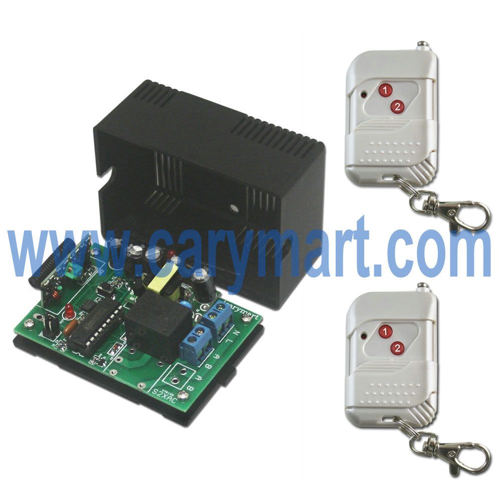
We recommend the model of 1 channel 220V power output controller switch (S1X-AC220+2C-2), you can buy 5 sets.
It can control lights, motors, fans, electrically operated doors/locks/windows/blinds/cars or other appliances with AC 100~240V. You can turn on/off the receiver with transmitter (remote control) from any place within a reliable distance (about 100m); the wireless RF signal can pass through walls, floors and doors. With characteristics of direct power output, you don’t have to provide additional power to remote-controlled device since device can get power from receiver if receiver is charged.
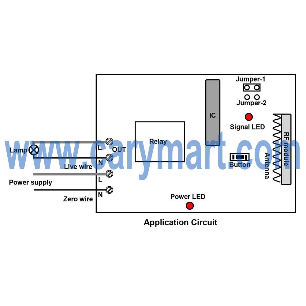
Wiring diagram is here. Wire light to L&N terminals of “OUT “terminal. Each light will wired to each receiver.
There are three working modes in it. They are toggle, momentary and latched modes. Here, you can choose latched because there are two buttons of transmitter.
Setting control mode Latched: Do not connect Jumper-1 and Jumper-2.
Press button 1: Turn on light.
Press button 2: Turn off light.
You can switch off/ on any light at your option.
2014/01/26
Customized Time Delay Remote Controller for 6V Light
This 1 channel dc RF remote control switch features in controlling relay off time delay. Delay time can be customized according to actual requirement. It is widely applied to control lights, motors, fans, electrically operated doors / locks / windows / blinds or other electrical devices. It is activated in 6V power supply. You need provide us with the delay time you want when ordering. E.g. delay time: 20 seconds or 1 hour or 20 minutes… The delay time is not adjustable freely. Its working current is 10ampere and working distance is 100m (300ft).

It has normally open and closed contact. It controls various lights, fans or motors with voltage AC110~240V or DC0~28V. Here is the alternate current device wiring diagram and the wiring diagram of direct current device which not share the same power supply with receiver.

Of course, if you want to remote control direct current device which shares the same power supply with receiver, you need to do some different wiring from above wiring. Suppose that you want to remote control 6V lamp. So you don’t have to supply additional power for led lamp because led lamp will get power from powered receiver as long as you wire lamp to the receiver.
Here is the wiring procedure of 6V lamp which shares the same battery with receiver. The red wire from the lamp is connected to the C terminal of the receiver and black wire from the lamp is connected to the negative electrode of the power supply. The positive wire of the supply power is connected to B terminal and positive electrode of the receiver. The negative electrode of the power supply of power supply and receiver are connected together.

We set its delay time 20seconds.
Press button 1: Turn on the lamp. After 20seconds, turn off the lamp by itself.
During the delay time, press button 2: Turn off the lamp straightway.
2014/01/09
How to Remote Control 6V LED Lights
Question from customer:
I’m looking for a wireless remote that I can use to create a simple on off switch to 12 led light fixtures connecting to a 6V battery at different places around my home. Do you have any suitable remote controller for me?

Answer:
We recommend model 12 Channel DC6V Remote Controller – 1 Transmitter & 12 Receiver (12S1UB-DC06&1CV-12). This RF remote controller has the special ability to learn remote codes, allowing it to be used in one-transmitter-to-many-receivers system. That is to say, you only need a transmitter to control 12 receivers. 6V is added to receiver as activated power. It operates in toggle, momentary, and latched mode (set the mode as you like freely). It is great for hard to reach lights or other DC/AC electrical devices, remote distance can be 500m (theoretically). And it is applied for controlling lights, motors, fans, electrically operated doors / locks / windows / blinds / cars or other appliances with voltage AC110~240V or DC0~28V.

Here is the wiring diagram. LED lamp is connected to normally open terminals B&C. And add a wire between terminals “B&-“ and another wire to terminals “C&+”. At last, wire a plug to terminals “+&-“. LED lamp and receiver will share the same power supply——6V.

It’s easy to set and operate. You can press each button on the transmitter to control the corresponding receiver to control LED lamp.
2014/01/08
DC12V Remote Switch Controls Winch Motor Rotation and Lamps On and Off
Question from customer:
I am in need of a controller. I will be using this to control a winch on my pickup and some lights. So I need one button momentary for line in, one button momentary for line out, and 2 buttons on/off for lights.
Answer:
4 Relay multi-mode On / Off remote controller (S4U-DC12 & C-4) is very suitable to you. There are 4 channels for more than one device. It has universal controlling mode, including toggle, momentary, latched, and Momentary+toggle modes. The maximum current is 10A and working distance is about 100m. It features in controlling lights, motors, fans, electrically operated doors / locks / windows / blinds / cars or other appliances with AC110~240V or DC0~28V. You can turn on/off the receiver with transmitter (remote control) from any place within a reliable distance; the wireless RF signal can pass through walls, floors and doors.

According to your requirement, Channel 1~2 are for motor and Channel 3~4 are for lamps. At first, please see the wiring. Wire winch motor to “B” terminals of relay 1 and relay 2. That makes motor rotate in two different directions. Supply power to winch motor. Secondly, wire two lamps to “B” terminals of relay 3 and relay 4. Supply power to lamps.

Thirdly, learning Momentary (Channel 1~2) + Toggle (Channel 3~4) control mode: When the receiver is in the status of LEARNING, press button 3 of the transmitter.
When you press and hold button 1, winch motor rotates in positive direction; release it, winch motor stops.
When you press and hold button 2, winch motor rotates in reverse direction; release it, winch motor stops.
When you press button 3, turn on lamp 1; press button 3 again, turn off lamp 1.
When you press button 4, turn on lamp 2; press button 4again, turn off lamp 2.
2014/01/07
Underground Garage Door is Controlled Car Alarm System
Question from customer:
I need a radio system for switching a receiver of an underground garage, by a concrete slab with steel reinforcement and about 30 meters Distance 1st floor. The receiver may be 220 volts. Transmitter I want to act with an external contact. (Connection to a car alarm system).
Answer:
We recommend the 1 channel high power receiver (S1PUA-AC220-ANT2) and long range transmitter with extended wires (CB-2N). The receiver is activated by ac 220V, which is about 2000m working distance with external extended antenna. The wireless RF signal can pass through walls, floors and doors. It works with the long range transmitter, which features in two external wires because connection of two wires is its triggering method.

According to your requirement, we drew a wiring diagram.

Wires on the transmitter should be connected to the contacts of car alarm system.

The normally open contacts A&B of receiver should be connected to the garage door motor. And supply additional 220V power other than receiver.
Setting latched mode to this receiver.
When the contacts of two wires are closed, the transmitter is triggered and then transmits an rf signal “ON” to activate the receiver. After the receiver receives the signal, contacts A&B are closed; the motor starts to work to open the garage door.
When the contacts of float switch are cut, the transmitter is triggered and then transmits an rf signal “OFF” to deactivate the receiver. After the receiver receives the signal, contacts A&B are cut; the motor stops working to shut down the garage door.
2014/01/06
Latched Mode Remote Controller Apply for Device Control Another Device (Float Switch control Water Pump)
Question from customer:
When the tank is empty my float switch makes contact and stays in this mode till the tank is full.
What I need is for the transmitter to activate the receiver and hold it in the on position till the float switch interrupts the transmitter and releases the receiver. I need a receiver which is only activated as long as the transmitter sends a signal. Or I need a way to make the transmitter send a signal when the float switch makes contact, then interrupts this signal and sends a second signal when the float switch interrupts contact.


Answer:
We recommend the model of normally open latched 2000m remote controller (S1L-DC12-ANT2 & CB-2N). The receiver is with magnetic antenna and only one working mode—latched mode. It is activated the 12V power. The transmitter is designed with novelty. There are two wires extending from transmitter. The triggering method is connection and disconnection of two wires. When two wires are connected, “ON” signal will be sent out. When two wires are connected, “OFF” signal will be sent out.

Wires on the transmitter should be connected to the contacts of float switch.

The normally open contacts B&C of receiver should be connected to the water pump.

When the tank is empty, the contacts of float switch are closed, the transmitter is triggered and then transmits an rf signal “ON” to activate the receiver. After the receiver receives the signal, contacts B&C are closed; the pump starts to work.
When the tank is full, the contacts of float switch are cut, the transmitter is triggered and then transmits an rf signal “OFF” to deactivate the receiver. After the receiver receives the signal, contacts B&C are cut; the pump stops working.
2014/01/03
315Mhz/433Mhz 9v Remote Controller for Electron Microscope’s Motors
Question from customer:
I use a manual switch to control 4 9V motors of my electron microscope and each motor works in 150ma (0.15a). In addition, only one motor works when I press button of remote control each time. Now I want to remote control them, have you got any suitable remote for me?
Electron microscope:

Manual Switch of microscope:

Answer:
We thought this 8 channel rf remote transmitter & receiver is very suitable for you . It can be used to control at most 8 on / off electrical devices. With characteristics of strong anti-interference, reverse power protection and over current protection. Three voltages dc9v, dc12v and dc24v are provided to choose. It is widely applied to control many kinds of lights, electrically operated doors / gates / windows / blinds and so on. It works with 8-button transmitter and their transmitting distance can reach to 500m.

This is the wiring diagram.

Wire each motor to the normally open terminal “B”. According to the diagram, you can do wiring like above. Even though there are 8 working modes in it, you can choose ”Momentary mode” which is applied in motor’s rotation.
Control mode Momentary (Channel 1~8): Press and hold -> On; Release -> Off.
Press and hold button 1: Motor 1 rotates in positive direction
Release button 1: Motor 1 stops rotation
Press and hold button 2: Motor 1 rotates in reverse direction
Release button 2: Motor 1 stops rotation
Press and hold button 3: Motor 2 rotates in positive direction
Release button 3: Motor2 stops rotation
Press and hold button 4: Motor 2 rotates in reverse direction
Release button 4: Motor 2 stops rotation
Press and hold button 5: Motor 3 rotates in positive direction
Release button 5: Motor 3 stops rotation
Press and hold button 6: Motor 3 rotates in reverse direction
Release button 6: Motor 3 stops rotation
Press and hold button 7: Motor 4 rotates in positive direction
Release button 7: Motor 4 stops rotation
Press and hold button 8: Motor 4 rotates in reverse direction
Release button 8: Motor 4 stops rotation
Only one motor works when you press the corresponding button on the remote.
2014/01/02
220V Transceiver Turn on/off LED Lamp Via Transformer
Question from customer:
I want to put a 220v Transceiver to turn on / off the power of a transformer of led lighting (to avoid the transformer is always on), this will make me a remote control switch. I want a basic on / off function product.
Answer:
1 channel ac power direct output remote switch (S1X-AC220+C-2) is suitable for you. Its remarkable feature is ac power direct output, that is to say, you don’t have to supply additional power to being controlled device because it can get power from powered receiver. It controls lights, motors, fans, electrically operated doors/locks/windows/blinds/cars or other appliances with AC 100~240V range. You can turn on/off the receiver with transmitter (remote control) from any place within a reliable distance (about 100m); the wireless RF signal can pass through walls, floors and doors.

Wiring diagram is here. Wire transformer to L&N terminals of “OUT “ terminal. Then wire lamp to the transformer.

To avoid transformer being always on, you can use transmitter to remote control it. There are three working modes in it. They are toggle, momentary and latched modes. Here, you can choose latched because there are two buttons of transmitter.
Setting control mode Latched: Do not connect Jumper-1 and Jumper-2.
Press button 1: Turn on the transformer, terminal OUT outputs AC power to switch on lamp.
Press button 2: Turn off the transformer, terminal OUT no output to switch off lamp.
2013/12/31
1 Channel AC Remote Controller for Contactor
Someone would like a remote control to switch on and off his lamp via controlling a contactor. He drew a picture to illustrate his idea. Maybe it is not so convenient to him to remote control lamp directly, so he choose to control his lamp via a contactor.

We recommend him a 1 channel AC remote switch with memory function (S1MU-AC220+C-2). This 1 channel ac rf memory remote controller operates in toggle, momentary and latched control mode (set the mode as you like freely). With function of memory, if the power is cut off, the relay will return automatically to the previous status after the power is restored. It is great for hard to reach lights or other electrical devices, remote distance up to 100m (theoretically). It is applied to control lights, motors, fans, electrically operated doors / locks / windows / blinds / cars or other appliances with voltage AC 110~240V or DC 0~28V.

According his requirement, we have this following diagram. Initial state: A, B = Normally Closed; B, C = Normally Open. Wire contactor to normally open contact B&C terminals. And Wire a lamp to contactor and install a switch for lamp (See the original picture).

There are 3 working mode of remote control. They are toggle, momentary and latched modes. We suggest that he should set latched mode because this remote works with a 2-button transmitter.
Setting control mode Latched: Do not connect Jumper-1 and Jumper-2.
Control mode Latched: Press -> On, another relay Off; Press another button -> Off.
Press button 1: Turn on the contactor to turn on lamp (connect B and C, disconnect A and B)
Press button 2: Turn off the contactor to turn off lamp(disconnect B and C, connect A and B)
2013/12/30
0~28V or 110V~240V Device is Remote Controlled by 8 Transmitters and One Receiver
Question from customer:
I want to install a set of wireless remote controls, include 8 transmitters in 8 different places (max. 500 m) and one receiver in a specific location. The transmitter transmits a wireless signal to control a closed contact.
Answer:
We recommend normally open/closed contact toggle remote control (S1T-DC12-ANT2+CB-1). According to your requirement, you can choose 8 transmitters (CB-1) to work with the receiver. There are normally open/closed contacts in it which are able to connect device activated by DC 0~28V or AC110~240V. With external extended antenna, its working distance has reached 2000M in the open field. You can use 8 transmitters to remote control receiver from different directions.

This kind of remote control is activated by DC12 power supply. Toggle Mode is the only working mode of it. Here is the wiring diagram. Initial state: A, B = Normally Closed; B, C = Normally Open. Wire your device to normally closed contact A&B terminals. If you do this, your device is turned on always, that is to say, your device will on work all the time.

When you press button on the transmitter (connect B and C, disconnect A and B), turn off device; When you press button again (disconnect B and C, connect A and B), turn on device.
2013/12/27
Remote Control 2 Lamps 100M 3 A—Latched Mode
When you want to remote control one more AC devices, you may think about 2 channel remote receiver. This kind of Latching 2 channel remote switch (S2L-AC110~240V + C-1) may be suitable for you. It is activated by AC110V~240V power supply, so being controlled devices will get power from powered receiver. The maximum current output is 3 ampere. The Coding type of receiver is learning code. You can remote control any electric devices within 100M (No obstacles).

Look at the following wiring diagram. We try to introduce 2 lamps controlling of this kind. First, we connect the neutral wire to the terminal “1”, and the live wire to the terminal “2”. Second, we connect the lamp 1 to the terminal “5” and the neutral wire. Third, we continue to connect the lamp 2 to the terminal “4” and the neutral wire.

Latching mode is the only working mode of this remote. So we can do the following operation.
1) Press button C: Turn on the lamp 1, turn off the lamp 2.
2) Press button B: Turn on the lamp 2, turn off the lamp 1.
3) Press button A: Turn off the lamp 1 and the lamp 2.
You can remote control any AC electric appliances other than lamps. It is very convenient to you because you don’t have to supply any power to controlled appliances.
2013/12/26
Latched Mode Remote Controller for Lamp Controlling
The 1 channel Latched mode RF remote control operates in AC110V ~220V and 315/433MHz. Through retrofitting, this kind of remote control made a little changes compared with the original remote. Two kinds of receiver style, one is AC 110V (AC 100~120V), widely used in US, Canada…; the other is AC220V (AC 200~240V), used in UK, France…. The Coding type of receiver is learning code. Maximum working current for each channel is 3 ampere instead of 4 ampere of original one. The working distance is 100M.

You can control on/off, open/close of universal electrical devices. Applications include gate remote control, motor remote control, garage door remote control, light remote control, etc. We will take ac light remote controlling for an example. Look at the following wiring diagram. From the interior analogue circuit, we connect the neutral wire to the terminal “1”, and the live wire to the terminal “2”. And then connect the lamp to the terminal “5” and the neutral wire.

Latched mode is the only working mode of it. As regards the latched mode, it is motivated by relay group. (Latched (Press button 1-> On; Press button 2 -> Off)) So we prepare a 2-button transmitter for you to remote control it. All you need to do is just press slightly the button on the remote. You press button 1 to turn on lamp; press button 2 to turn off lamp.
2013/12/24
Long Range Remote Control Appliance
Question from customer:
I want to turn an appliance off and on in a room in my house 120ft from the room with the transmitter. Does the appliance plug into the receiver and the receiver plug into an outlet?
Answer:
We recommend 3000ft long range ac direct output remote controller (S1X-AC220-ANT2 & CB-2). The remarkable feature of this remote controller is that 220V power direct output, that is to say, appliance plugs into receiver directly and gets 220V power from powered receiver( receiver is plugged into an outlet.) The maximum current of its relay is 10 ampere which is suitable for some appliances. The working distance is longer than any other remote, which is about 3000ft in the open field. 3000ft is long enough for your remote controlling.

At first, it is the wiring. Look at the following wiring diagram. For instance, we remote control a lamp. We just need to wire lamp to “L&N” terminals of “OUT”. That is very easy. And supply ac 220V to receiver. Then lamp can get power from powered receiver.

And this receiver works with two-button long range transmitter. There are three working modes in it. They are Toggle, Momentary, and Latched modes. If there is only a device, we recommend setting latched mode.
Setting control mode Latched: Do not connect Jumper-1 and Jumper-2.
Press button 1: turn on the lamp.
Press button 2: Turn off the lamp.
2013/12/23
Contactor's Remote Controlling
Question from customer:
I want to use the remote control to replace the button of my contactor. Since the switch will be activated rarely, is it possible to test the communication with the remote to be sure that the transmitter’s battery and receiver work correctly?

Answer:
We came up with a good idea that it can replace your manual switch to remote control contactor and to test whether the transmitter’s battery and receiver work correctly. So we recommend normally open/ closed 2 channel AC remote controller (S2U-AC220+C-2). The normally open/closed contact terminals are applied to universal power supply. In other word, normally open /closed contact terminals are as a switch for device. You need to supply DC or AC power to your controlled devices. The maximum current is 10ampere for each channel and its working distance is about 100m.

We got a plan for your problem. At first, it is the wiring. Look at the following wiring diagram. A&B terminals are the normally closed terminals. B&C terminals are normally open terminals. Being controlled devices will be connected to normally open terminals. It means that it won’t work in off-state when you disconnect the circuit. We will connect an AC lamp to relay 1 and button of contactor to relay 2. They are supplied to the same power.

And this receiver works with two-button transmitter. There are four working modes in it. They are Toggle, Momentary, Latched, Momentary + Toggle. We set Toggle mode. You want to make sure the transmitter’s battery and receiver correct working but the switch will be activated rarely. You see, the lamp is for test. When you want to test remote controller, you press button 1, if the lamp is switched on, then the transmitter and receiver work. When you press button 1 again, turn off lamp. Press button 2, turn on the contactor, press button 2 again, turn off the contactor.
2013/12/18
How to Remote Control 2 AC Lamps On and Off by 2 Channel Toggle Controller
When you want to remote control one more AC devices, you may think about 2 channel remote receiver. This kind of toggle 2 channel remote switch (S2T-AC110~240V + C-1) may be suitable for you. It is activated by AC110V~240V power supply. The maximum current output is 3 ampere. The Coding type of receiver is learning code. You can remote control any electric devices within 100M(No obstacles).

Look at the following wiring diagram (1). We try to introduce 2 lamps controlling of this kind. First, we connect the neutral wire to the terminal “1”, and the live wire to the terminal “2”. Second, we connect the lamp 1 to the terminal “5” and the neutral wire. Third, we continue to connect the lamp 2 to the terminal “4” and the neutral wire.

Toggle mode is the only working mode of this remote. So we can do the following operation.
1) Press button 1, turn on the lamp 1; Press button 1 again, turn off the lamp 1.
2) Press button 2, turn on the lamp 2; Press button 2 again, turn off the lamp 2.
You can remote control any AC electric appliances other than lamps. It is very convenient to you because you don’t have to supply any power to controlled appliances which will get power from powered receiver.
2013/12/16
AC110V~220V Output Remote Control Connection and Application
The 1 channel RF remote control operates in AC110V ~220V and 315/433MHz. Through retrofitting, this kind of remote control made a little changes compared with the original remote. Two kinds of receiver style, one is AC 110V (AC 100~120V), widely used in US, Canada…; the other is AC220V (AC 200~240V), used in UK, France…. The Coding type of receiver is learning code. Maximum working current for each channel is 3 ampere. The working distance is 100M.

You can control on/off, open/close of universal electrical devices. Applications include gate remote control, motor remote control, garage door remote control, light remote control, etc. We will take ac light remote controlling for an example. Look at the following wiring diagram. From the interior analogue circuit, we connect the neutral wire to the terminal “1”, and the live wire to the terminal “2”. And then connect the lamp to the terminal “5” and the neutral wire. Actually, if you wire ac motor to the lamp position of following diagram, then you can control ac motor on and off.

Toggle mode is the only working mode of it. (Toggle (Press -> On; Press again -> Off)) All you need to do is just press slightly the button on the remote. You press button to turn on lamp; press button again to turn off lamp.
订阅:
博文 (Atom)