Hot Posts

显示标签为“irrigation”的博文。显示所有博文

2013/07/16

1 Channel High Power Direct Power Output Remote Switch for Irrigation System

Tom is trying to design and build a remote switch system for his sprinkler system. He needs to use the sprinkler controller (12v output for on) to trigger a transmitter to switch a 12v operated valve on the other side of the yard (about 300m away.) He has mains power at both locations but the underground 12v wire from the controller has been damaged so he would like to build a remote system to save putting new conduit for around 300m across the yard.
The easy part would be the receiver end because he would only need a 12v power supply. The hard part will be getting the transmitter to switch on when the sprinkler controller switches on (12v).
sprinkler-controller
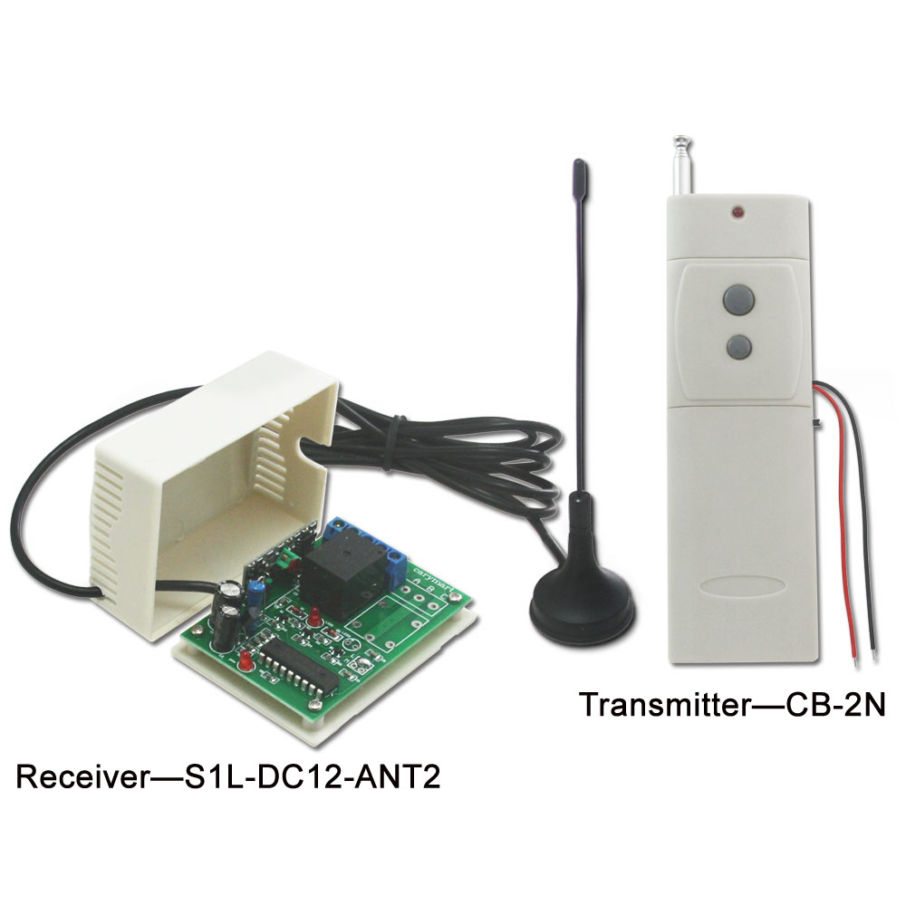
We recommend direct power output high power long range remote control kit—S1PX-DC12-ANT2+CB-2V. The remarkable feature of this kit is that its transmitter is triggered DC power 5~28V input. That is to say, the transmitter will send out RF signal to receiver as long as it gets a 5~28V voltage from a device. Besides this advantage, its working distance is up to 2000m (6000ft). And the working current is 30amp. RF signal can pass through doors, walls and other obstacles.
remote control
Look at the following simulated diagram. The sprinkler control controls the valve box through the underground electrical wire initially. Unfortunately, the wire has been damaged. However, customer is unwilling to put new conduit for about 300m across the yard.
original wiring
So using our product to solve this problem is a wise choice. We connect the black wire of transmitter to the common wire of sprinkler controller; Connect the red wire of transmitter to wire from controller to valve. On the other hand, in the control valve box, valve common wire is supposed to be connected to the negative terminal of receiver; valve wire should be connected to the positive terminal of receiver. (As the following application circuit shown)
application circuit
Wiring modification
When you switch on sprinkler controller, the transmitter will be triggered by 12V voltage from sprinkler controller and sent out RF signal to indicate receiver to work. The valve is open and it starts the irrigation. Likewise, you switch off sprinkler controller, the triggered transmitter will indicate receiver to stop working. The valve is closed and it stops the irrigation.
There is no need to put new wire between sprinkler controller and valve control box. It is no longer the hardest part of getting transmitter to switch on when the sprinkler controller switches on.
irrigation modification

2013/03/29

Pumping water automatically with remote control system

   James starts to manage a farm since this year. He needs to pump water to tank in the water tower for irrigation every day. At the beginning, James installed a water level sensor which is connected a gadget with two indication lights. When red light flashing, it means that the water level is low. He needs to switch on the water pump by hand. When the green light flashing, it means that the water level reaches the high level. Gradually, it is tired of him to run to 1000m away to monitor whether water level in the tank gets low or high and switch on or off the pump motor every day. So James would like something will send signal which can make switch of the motor turn on to pump water automatically. So how can he combine pump motor and water level senor with remote controller? Recently,  he just found a new remote control kit promoted , model 0020522 (S1L-DC12-ANT2+CB-2N). With the combination of those two gadgets, using a water level senor to remotely control the water pump motor is no longer a Gordian knot. This is a long distance remote controller kit. Transmitting distance is up to 1000m in open field.


   In addition, the supplier said the major characteristic of CB-2N is that it has two extended wires, which is wired to the electric device. When two wires are connected, the rf signal ”ON” will be sent out; When two wires are disconnected, the rf signal “OFF” will be sent out. That is easy to operate.


    The extended wires on transmitter should be connected to the water level sensor. The red wire from the motor is connected to the C terminal of the receiver and black wire from the motor is connected to the negative electrode of the power supply. The positive wire of the supply power is connected to B terminal and positive electrode of the receiver. The negative electrode of the power supply of power supply and receiver are connected together.


   When the water level gets low, it makes the contacts of water sensor are closed; with extended wires of transmitter connection, the transmitter is triggered and transmits an RF signal “ON” to the receiver. The receiver output contacts are closed after received the signal, the pump begins to pump water. When the water gets high, it makes the contacts of water sensor are cut; the transmitter is triggered and transmits an RF signal “OFF” to the receiver. The receiver output contacts are cut after received the signal, the pump stops pumping water.